
FORMULATION · STORAGE · DEPLOYMENT
From separated components to controlled pumping.
An engineering analysis of every DISE-HP element, how it is stored, prepared and released to the pump without confusing shelf-life protection with the programmed downhole induction gate.

Original formulation architecture from the DISE engineering presentation. Values shown are development specifications unless independently validated.
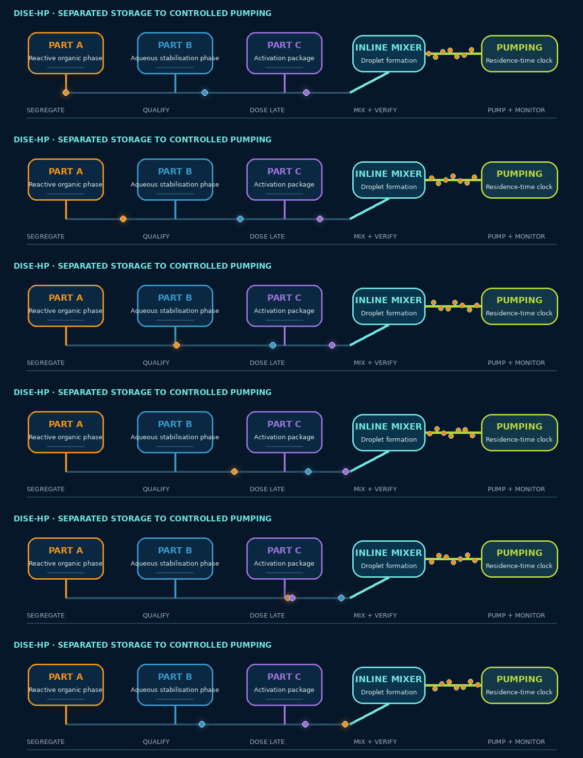
SYSTEM ARCHITECTURE
Three packages, three different responsibilities.
The safest architecture keeps long-term logistics, droplet stabilisation and deployment activation as separable control layers. Exact chemical identities and concentrations are selected only after compatibility, kinetics, rheology and HSE screening.
Part A · Reactive organic phase
Hydrophobic monomer and crosslinker candidates, their supplier-qualified storage inhibitor, and compatible organic-phase additives. Its role is to provide a low-viscosity precursor that becomes the crosslinked particle. The benchmark branch is Styrene–DVB; multifunctional alternatives remain formulation candidates, not interchangeable ingredients.
Part B · Aqueous stabilisation phase
Engineered brine, a high-temperature protective colloid and surface-active silica. This phase controls bulk transport rheology, droplet formation, interfacial separation and heat capacity. Density adjusters, buffers or compatibility additives are admitted only when their effect on kinetics and the interface is measured.
Part C · Activation package
The selected oil-soluble thermal initiator and deployment-specific induction-control chemistry, stored according to supplier safety and compatibility requirements. Part C is not the shelf-life inhibitor system and is introduced late enough to limit unnecessary surface residence time.
Protective colloid
Provides rapid steric repulsion and dynamic interfacial elasticity. It must remain effective in the selected brine, temperature and shear envelope without raising complete-suspension viscosity above the challenge limit.
Pickering silica
Creates a persistent physical barrier during the intermediate-conversion tack phase. Required coverage, wettability, concentration and compatibility are measured; silica does not justify describing the treatment as literally solids-free.
Control additives
May include pH control, density adjustment, defoaming or corrosion-compatible ingredients. Each additive is treated as a possible kinetic and interfacial perturbation and must pass a one-at-a-time and integrated compatibility screen.
STORAGE PHILOSOPHY
Supplier-qualified storage comes before formulation convenience.
DISE does not prescribe one universal inhibitor loading, oxygen concentration, storage temperature, atmosphere or container material. Each raw material remains inside its manufacturer-qualified envelope until substance-specific hazard, stability and compatibility data support a controlled deviation.
Retain supplier inhibitor, original compatibility controls and traceable lot identity. Protect from unqualified heat, contamination and incompatible metals or transfer materials.
Control microbiological risk where relevant, brine composition, pH drift, silica sedimentation or colloid degradation. Define re-homogenisation and rejection criteria.
Segregate initiator and induction-control chemicals from incompatible materials. Apply supplier temperature, packaging, venting, inventory-age and emergency-response requirements.
PREPARATION FOR PUMPING
A gated sequence, not a single bulk-mixing step.
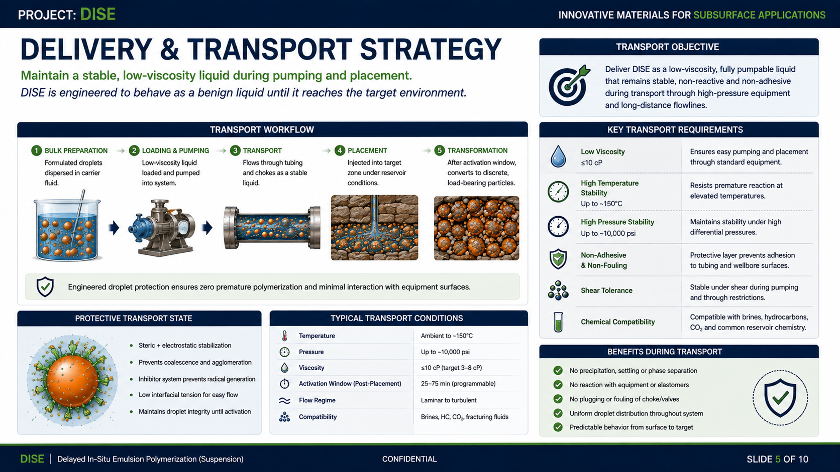
The presentation workflow is used as a visual overview. Statements such as zero premature reaction remain objectives to be verified by the acceptance gates on this page.
Confirm the selected chemistry is qualified for the actual brine, hydrocarbon or CO₂ exposure, temperature trajectory, pressure, materials of construction and planned residence time.
Verify clean, dry or conditioned transfer paths as specified; remove incompatible residues; confirm seals, elastomers, metals, filters, mixers, pumps and emergency isolation arrangements.
Make the aqueous stabilisation phase under controlled order of addition. Confirm composition, pH where relevant, homogeneity, absence of unacceptable foam or sediment and release for emulsification.
Use controlled inline shear to generate the target droplet distribution without overheating or entraining unacceptable gas. Record flow ratio, mixer energy and temperature.
Measure complete-suspension viscosity and representative D10/D50/D90. Reject or rework if viscosity, oversized droplets, agglomeration or phase separation fall outside the job specification.
Dose the calibrated activation package sufficiently close to pumping to minimise surface dwell while preserving reliable mixing. Start the residence-time clock at the defined activation point.
Confirm flow ratios, temperature, pressure, viscosity, batch identity, calculated induction margin, sample retention and stop/flush readiness before opening the route to the well.
Trend pressure, flow, temperature, cumulative volume and elapsed time. Compare the actual thermal and residence history with the validated operating map rather than relying on one nominal trigger temperature.
PUMPING ENVELOPE AND CONTROLS
Release only inside the overlap of every qualified envelope.
Hydraulic envelope
Complete suspension ≤10 cP across the agreed placement shear and temperature range; no problematic yield stress; controlled differential pressure through representative restrictions. The 3–8 cP value is a formulation aim, not a demonstrated result.
Morphology envelope
Controlled D10/D50/D90 before and after shear, no operationally significant macro-coagulum, and acceptable response after the longest credible pause and restart.
Kinetic envelope
A 25–75 minute programmed induction window maintained across measured thermal histories, initiator variability and reaction self-heating, with a defined minimum surface safety margin.
Gravitational envelope
Measured density and shrinkage through conversion show no functionally significant settling or creaming during the specified pause/restart scenario.
Materials envelope
No unacceptable swelling, corrosion, extractables, inhibitor loss, fouling or adsorption in tanks, hoses, mixers, seals, valves, pumps or completion hardware.
Operational envelope
Actual batch age, temperature, elapsed activation time, flow ratio and pressure remain traceable and inside the job model. A deviation triggers hold, isolate, sample or flush—not an assumption of continued stability.

HOLD, STOP AND FLUSH LOGIC
The safest batch is the one that can still be stopped.
The field procedure must define maximum activated surface residence time, allowable pause duration, isolation boundaries, displacement fluid, flush volume, waste route and the point beyond which material cannot be safely recirculated or returned to storage.
Unexpected temperature rise, pressure trend, ratio deviation, viscosity increase, visible phase change, abnormal pump load, foam, agglomerate or loss of timing traceability.
Recalculate remaining induction margin from the recorded thermal and residence history; verify homogeneity and pressure response; restart only within the validated pause/restart envelope.
Reject when identity, storage history, mixture ratio, PSD, viscosity, activation time or compatibility status cannot be demonstrated—or when any safety-critical deviation exceeds the qualified recovery procedure.
ENGINEERING STATUS
A deployment architecture, not yet a field operating procedure.
Exact recipes, container specifications, storage limits, shear energy, dosing rates, flush chemistry and emergency controls must be derived from substance-specific data and confirmed by the staged DISE validation programme.

